
The idea for this reader comes from my own frustrations, and from the comments of other list members when discussing the code reading process. As you know, the EEC-IV has available a variety of self-tests, and trouble-shooting procedures. I'm not going into the procedure here, as many others have written excellent articles on the procedure and the codes themselves. This project gives the driver the ability to check his codes from the driver's seat, at any time. This makes it more convenient in inclement weather, and avoids having to run back-and-forth between the driver's seat and the underhood area.
The test unit is handheld, and connected to the car's wiring harness through the glove box. A four-wire disconnect in the glovebox allows the testing unit to be removed for use on another car.
Materials list (Radio Shack part numbers):
Experimenter's box (3.25x2.125x1.125) p/n 270-230 $1.47
4-wire disconnect p/n 270-027 $2.49
Snap-in lamp assembly p/n 272-332C (two pack, but you only need one) $1.99
SPST Rocker switch p/n 275-690 (2) $1.99 ea
color-coded wires (3 or 4 colors) $3.98
Total: $9.93 (plus tax)
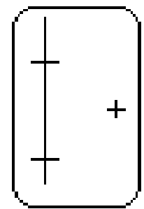
Take the plate from the project box, hold it so that the long side is vertical (like a playing card). Along the left side of the plate, draw a vertical line about 12mm from the left edge. Along this line, you will place two marks: the first is 21mm from the top, the second is about 37mm below that one. These mark the hole centers for the two rocker switches. The center for the lamp is about 8-9mm from the right edge, and centered vertically. See the attached image, is should help. I tried to draw it to scale, so that you could use it as a template.
Drill holes for the switches and the lamp. The packaging on the lamp states that it fits _inch hole. I used a _ inch drill bit, but the hole was a little too big, so be careful. I'm not sure what size the hole for the rockers is - I didn't have a bit that size, so I ground the hole larger with a rotary file. This resulted in a better fit than I got with the lamp. With a small file or saw, cut a small notch in the holes to match the key-type notch on the switches, to keep the switches from twisting once mounted. Install the lamp and the switches in the plate.
Drill a small (~ _ inch) hole in one of the short (2.125") sides of the box. Thread four wires of different colors through the hole. I used red, green, and two black wires. You should have about 18 inches of each wire.
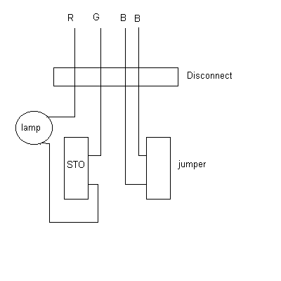
The two switches are labeled "STO" and "Jumper". Take one of the leads from the lamp, and solder to one terminal of the STO switch. I choose the top switch for STO. Connect the other wire from the lamp to the red wire that runs out the box. Connect the two black wires to either side of the Jumper switch.
Close the panel on the project box. The insides are done. At the ends of the four wires, connect the 4-wire disconnect. The matching side of the disconnect will connect to the car's wiring harness. Make sure that the red wire is attached to the disconnect so that the plug on the "car" side of the disconnect will be female. This is to keep the positive terminal from being exposed when the testing unit is unplugged from the car's harness.
If a second (matching) disconnect is purchased, you can attach test probes, alligator clips, spade terminals (whatever), so that you can use the unit on another car.
I haven't run the wiring for the car's harness yet, but here's the basic idea - The positive lead (red wire) will get power from a "hot" wire under the dash. The green wire attaches to the STO terminal under the hood. The two black wires form the jumper wire from the terminal on the multiplug (where the STO is) and the single wire hanging next to it. I am trying to find a source for a male plug that matches the STO multiplug - I'll keep you informed. Route the three wires (2 black, and one green) through the firewall, and into the glovebox. Keep the testing unit in the glovebox, too. Turn the car off, plug the tester in, switch both rockers on, and proceed with the tests. When the instructions say to "disconnect the jumper", switch the "Jumper" switch off.
Even though it is probably safe to leave the unit plugged in, in the glovebox all the time (with the switches off), I tend to be cautious about such things - unplug the disconnect when you aren't running your codes.
Now, you can run KOEO, KOER, "Goose" tests, and all your other favorites from the comfort of the driver's seat. OK, if you want to do a "wiggle test", lay the testing unit on the dash, or bring it out under the hood with you.


