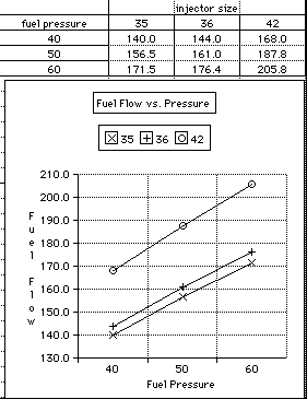

Power is made by air and fuel in the sufficient quantity and
ratio.
Fuel burn efficiency is quantified by "brake specific fuel
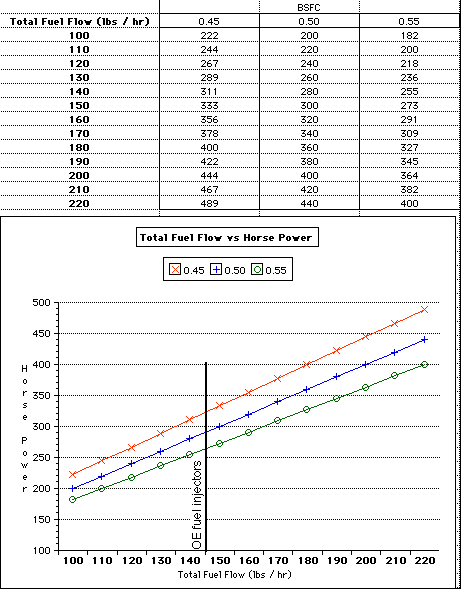
consumption" (BSFC). Reviewing the chart (fuel flow vs. horsepower)
relates injector size, BSFC, and horsepower. The experimentally
proven limit of crankshaft HP is about 290 HP (stock 36lbs/hr
injectors). For 36 lbs/hr (144 lbs / hr total) injectors this
shows a BSFC of about 0.50. The Fuel Pressure Analysis shows the
increase in total fuel flow by raising fuel pressure. These pressures
are the base fuel pressure at idle. A special "adjustable
fuel pressure regulator" is needed to change the fuel pressure.
Stock FORD 2.3 turbo engines are air flow limited. As air flow
increases the pressure drop increases exponently. When the cumlative
drops are balanced by the low pressure in the cylinder intake
stroke, equalibrum is reached and that is the maximum air flow
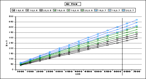
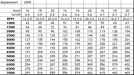
for the engine at that RPM. Reviewing the Air Flow analysis chart
the boost and volumetric efficiency are shown for the RPM range.
Volumetric Efficiency is the measure of what percentage of air
is drawn in vs the theoritical amount of air capacity. Porting
from the air inlet to the exhaust tip will increase the volumetric
efficiency from the stock amount of about 50% to maybe 70%. Note
that the turbocharger compressor is a major flow restriction above
about 300 cfm. One side effect of compressing the intake air is
that it is heated.
This chart shows the relationship between RPM, boost, BSFC, and air flow.
This table shows the Horsepower for three BFSC's at different fuel flows. Using the knowledge that our motors can make up to 280 HP (crankshaft), we can see that our motor efficiency is 0.50 BSFC. Note that this motor has a pretty modified air tract to flow this much HP. From the air/fuel ratio chart below it is clear that to make this much power we need to flow between 360 and 420 cfm depending on the air/fuel ratio. Remember the VAF ?, well the big one only meters 360 cfm. If we flow more air (pegged open), the amount of air is not being metered which means that the EEC can't flow the correct amount of fuel. Can you say LEAN MISSFIRE. This is why an air/fuel meter is so important on hi power motors.
This table shows the fuel flow per injector at three different air/fuel ratios for a series of air flows.
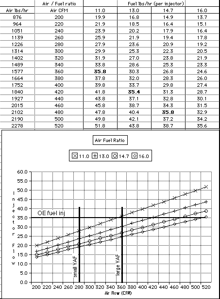
The fuel ratio is determined by: fuel pressure (relative to manifold pressure), injector size, and injector pulse width. The pulse width is determined by the tables in the EEC. During WOT the main input to pulse width is VAF output. When the VAF is flowing at the maximum rated flow, the EEC sends the maximum value from the table. As the flow increases above max rated flow no additional fuel is delivered causing a leaner condition. As the air / fuel mix moves from most power (11:1) to leaner condition the horsepower decreases.
