
There seems to be a lot of confusion in the archives between the Instrument Voltage Regulator (IVR) and the Anti Slosh circuit board. Other possible causes of gauges reading bad are wiring faults and faulty sending units.
The IVR is a TO-220 case transistor mounted
inside the back of the fuel and temp gauge. It is rated at +10V
output, and can be easily tested by checking the voltage on the
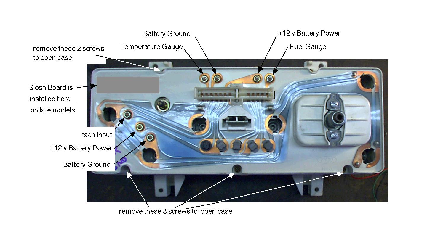
RED wire going to the Anti Slosh board. The recommended procedure
in the shop manual is to disconnect the fuel level sender (fuel
gauge nut shown above) and check for +10V at the sender connector.
The sender is a variable resistor that reads a high (full) of
19 ohms and low (empty) of 250 ohms. A bad IVR will cause BOTH
the fuel and water temp to read abnormal (usually low). A bad
Coolant temp sender will cause only the coolant gauge to read
low. The coolant sender also has a resistance of 19 to 250 ohms.
The IVR is inside the Instrument cluster, inside the fuel/temp
gauge and cannot be seen without taking the cluster apart. The
IVR will be difficult to replace because of its location and the
way its soldered to the fuel/temp gauge. The Ford recommended
fix is to replace the fuel/temp gauge assembly from the instrument
cluster. A replacement +10V regulator can be substituted for the
factory part, but it must be a high current regulator. The gauge
draws about 500mA at full tank, and full hot. Texas Instruments
does offer a +10V 1.2Amp regulator, that should work. (It's a
7810, NOT a 78L10 or a 78M10, those have less current capability)
I'd bet Radio Shack can get it,for you, if you order it. It's
no fun to change though.
A faulty Anti Slosh board will cause the fuel gauge read inaccurately
but will not affect the coolant level reading. The Anti Slosh
board consists of two transistors and an opamp. What this circuit
does is dampen the movement of the gauge to compensate for sudden
changes in the fuel tank level from braking, cornering etc. The
Anti Slosh board can be removed from the back of the instrument
cluster, and the fuel gauge will still work. You will not hurt
anything by doing this and you can verify whether the Anti Slosh
board is defective by doing so. Remember the orientation of the
YELLOW and GREEN wires and be sure to replace the nylon insulator
separating the two wires. The insulator is not necessary with
the Anti Slosh board removed.The Anti Slosh board is the PC board
velcro'd to the back of the instrument cluster. It has 4 wires
connecting it to the instrument cluster. The colors are:
Red: +10V input from the IVR
Green: Input to the Anti Slosh board comes from the fuel level
sender
Yellow: Output of the Anti Slosh board that drives the fuel gauge
Black: Ground
To remove the tach
remove the 3 nuts and spring washers and carefully remove tach
assy
To remove the speedo
remove the 2 screws and carefully remove the speedo assy
To remove the temperature / fuel gauge assy
remove the 4 nuts and spring washers and carefully remove, there
is a clear plastic "ear" under both the speedo and the
tach. If caution is used the temp/fuel gauge assy can be removed
without removing the other 2 gauges